


Productadvies
Uw e-mailadres wordt niet gepubliceerd. Verplichte velden zijn gemarkeerd *


Planetary Gearbox Explained: How It Works, Types, and How to Pick the Right One
Jun 10,2026
Gids voor geborstelde DC-motoren: hoe het werkt, belangrijkste specificaties en wanneer u er een moet gebruiken
Jun 04,2026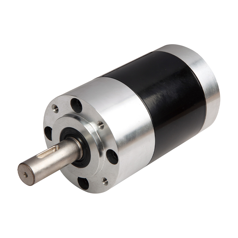
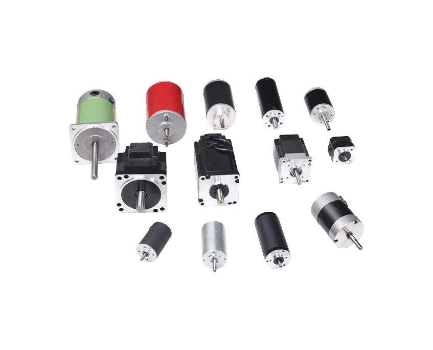
DC-reductiemotoren: de complete kopersgids voor typen, specificaties en selectie
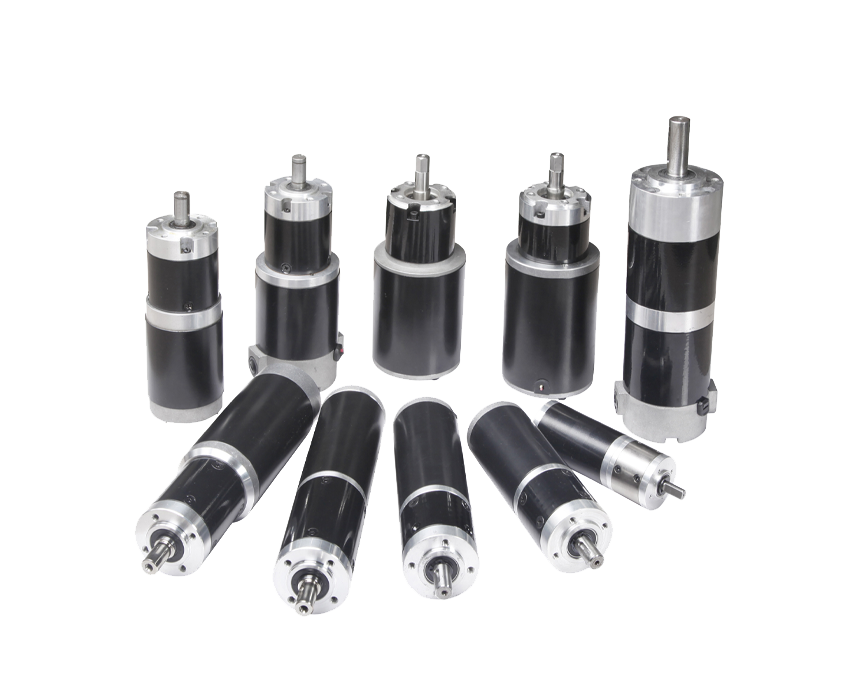
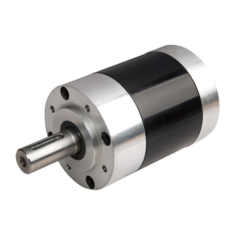
May 28,2026A planetary gearbox — also called an epicyclic gear train — is a compact mechanical system designed to transmit torque while reducing speed or increasing it, depending on configuration. Unlike a standard parallel-shaft gearbox, the planetary gear system arranges its gears concentrically, which is why it can pack so much power into such a small envelope. At its core, you have three functional parts working together at all times: the sun gear, the planet gears, and the ring gear.
The sun gear sits at the center and receives input from the motor. Surrounding it are typically three or more planet gears mounted on a rotating carrier. These planets mesh simultaneously with the sun gear on the inside and the ring gear (also called the annulus) on the outside. The ring gear has internal teeth facing inward. Because multiple planet gears engage both the sun and ring gear at the same time, torque load is split across several contact points — not concentrated on a single gear mesh like in spur or helical gearboxes. This is the fundamental reason planetary reducers can handle so much torque in a small housing.
In the most common operating mode, the ring gear is held stationary, the sun gear is driven by the motor (input), and the carrier delivers the output. The result is speed reduction and torque multiplication. Reversing the input and output elements changes the ratio and direction of power flow, giving engineers flexibility in system design.
Understanding the individual parts helps you evaluate quality, predict wear, and specify the right gearbox for an application. Here is what each component does and why it matters:
The sun gear is the primary input element. It is hardened and precision-ground to withstand high rotational speeds and the repeated stress of meshing with multiple planet gears simultaneously. Its tooth count directly determines the gear ratio — a smaller sun gear relative to the ring gear produces a higher reduction ratio.
Planet gears orbit the sun gear while also spinning on their own axes, which is why the motion resembles a solar system — hence the name. A well-designed carrier holds all planets in exact angular spacing (typically 120° apart for three planets) and uses needle roller bearings or bushings at each planet pin. Bearing quality here is critical: premature bearing failure inside the carrier is one of the most common causes of planetary gearbox breakdown.
The ring gear forms the outer boundary of the gear train. Its internal teeth mesh with the planet gears to complete the power circuit. In most configurations the ring gear is fixed to the housing, but in differential planetary systems it can also rotate. The ring gear typically has the largest tooth count, and its accuracy directly affects noise levels and backlash.
The output shaft is usually connected to the carrier. Housing material ranges from gray cast iron in heavy industrial units to aluminum alloy in servo-grade gearboxes where weight saving matters. Seal design at the output shaft determines ingress protection ratings (IP54, IP65, IP67) — an important spec for food processing, outdoor, or washdown environments.
The gear ratio formula for the standard configuration (ring fixed, sun input, carrier output) is straightforward:
Ratio = 1 + (Number of Ring Gear Teeth ÷ Number of Sun Gear Teeth)
For example, if the sun gear has 20 teeth and the ring gear has 80 teeth, the ratio is 1 + (80 ÷ 20) = 5:1. At 1,500 RPM input, the output delivers 300 RPM. If input torque is 10 Nm, output torque is approximately 10 × 5 × 0.97 = 48.5 Nm (assuming 97% stage efficiency).
For multi-stage planetary gearboxes, multiply the ratios of each stage together. Two stages of 4:1 and 5:1 produce a combined ratio of 20:1. Overall efficiency is also compounded: two stages at 97% each give 0.97 × 0.97 = 94.1% combined efficiency. The table below shows common ratio ranges and their typical stage configurations:
| Ratio Range | Stage Configuration | Typical Efficiency | Common Application |
|---|---|---|---|
| 3:1 – 10:1 | Single-stage | 97% – 98% | Servo drives, robotics |
| 10:1 – 100:1 | Two-stage | 94% – 96% | Conveyors, CNC axes |
| 100:1 – 1000:1 | Three- or four-stage | 88% – 93% | Heavy industrial, wind turbines |
For a quick sanity check during selection, always confirm the geometric constraint: Ring gear teeth = Sun gear teeth + (2 × Planet gear teeth). If this relationship is violated, the gears physically cannot mesh correctly.
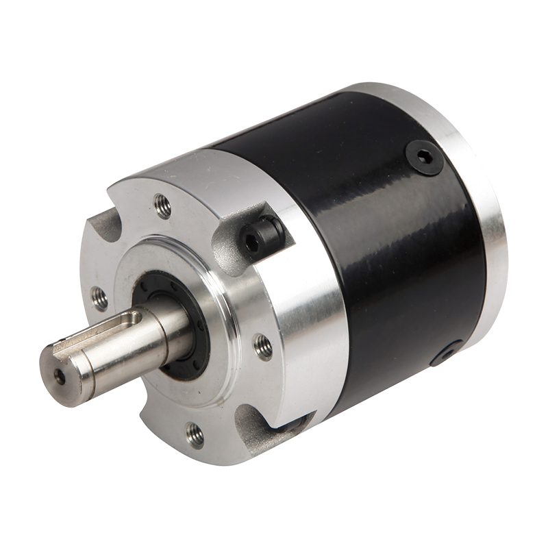
Not every planetary reducer is built the same. The housing configuration, output type, and internal gear geometry vary significantly between product families. Choosing the wrong type leads to premature failure, poor efficiency, or integration headaches.
The input and output shafts share the same axis. This is the most space-efficient layout and the default choice for servo motor applications. Precision inline gearboxes are rated in arc-minutes of backlash — values below 3 arc-minutes are standard for positioning systems, while ultra-precision designs achieve under 1 arc-minute for the most demanding motion control tasks. Typical ratios run from 3:1 up to 100:1 in one or two stages.
These add a bevel or hypoid gear stage at the output to redirect the shaft 90 degrees from the motor axis. They are the right choice for conveyors, mixers, and agitators where parallel shaft alignment is not possible. The bevel stage does cost some efficiency — expect 93–96% combined rather than the 97%+ of a pure inline unit.
Instead of a solid output shaft, a hollow-shaft design allows a through-rod, leadscrew, or actuator to pass directly through the gearbox center. This is common in rotary table drives, winding machines, and actuator assemblies where the driven component threads through the gearbox axis.
When a single stage cannot deliver the needed reduction, compound planetary gearboxes stack two, three, or four stages inside one housing. These units are used in applications like roll drives, agitators, and kilns where very high torque at low speed is required and physical space for a separate gearbox chain is limited.
Engineers frequently compare planetary gear reducers against worm gearboxes, helical inline gearboxes, and spur gear reducers. Each has a domain where it excels. The table below lays out the practical differences:
| Feature | Planetary Gearbox | Worm Gearbox | Helical Gearbox |
|---|---|---|---|
| Efficiency (typical) | 94% – 98% | 50% – 90% | 95% – 99% |
| Torque density | Very high | Moderate | Moderate |
| Backlash | Very low (precision grades) | Moderate to high | Low to moderate |
| Self-locking | No | Yes (high ratios) | No |
| Cost | Higher | Lower | Moderate |
| Best ratio range | 3:1 – 1000:1 | 5:1 – 100:1 | 1.5:1 – 10:1 |
Worm gearboxes make sense when self-locking is needed (such as in lifting systems) or when budget is tight and efficiency loss can be tolerated. Helical gearboxes are quieter at very high speeds and cheaper for moderate ratios. Planetary reducers win when torque density, precision, and efficiency all matter simultaneously — which is why they dominate servo-driven automation and electric vehicle drivetrains.
The planetary gear system's combination of compactness and torque capacity has made it the go-to solution across a wide range of industries. Below are the most common application areas and what drives their use of planetary reducers:
Selection errors are expensive — a gearbox that is undersized fails quickly, while one that is oversized wastes money and space. Work through these parameters in order before specifying a unit:
Start with your load torque, then apply a service factor based on duty cycle and shock load conditions. Most manufacturers recommend service factors between 1.5 and 2.5 for industrial applications. The selected gearbox must have a rated output torque that exceeds your calculated demand after the service factor is applied.
Divide your motor's nominal speed by the desired output speed to get the required reduction ratio. For single-stage units, ratios between 4:1 and 8:1 deliver the best balance of efficiency, size, and service life. If your required ratio exceeds 10:1, move to a two-stage design rather than pushing a single stage to its limits.
For conveying and hoisting applications, standard backlash (6–12 arc-minutes) is acceptable. For CNC axes and servo positioning, you need precision-grade units with 3 arc-minutes or less. Zero-backlash preloaded designs exist for the most demanding applications but come at a significant cost premium.
Verify that the gearbox input flange matches your motor's IEC or NEMA frame size, and that the output shaft diameter and keyway match your driven component. Many manufacturers offer hollow-bore or shrink-disc outputs that eliminate shaft-to-shaft alignment issues entirely.
Confirm that the gearbox thermal power rating exceeds your actual continuous power at your ambient operating temperature. For harsh environments, check the IP rating: IP65 or higher is required for outdoor or washdown duty. In food and beverage applications, look for NSF-certified lubricants and stainless steel shaft options.
Planetary gear reducers are reliable, but they are not maintenance-free. Understanding what typically goes wrong helps you build an effective maintenance program and catch problems before they cause unexpected downtime.
Most planetary gearboxes use grease for life or synthetic oil with scheduled changes. Using the wrong viscosity, allowing oil level to drop, or neglecting oil change intervals at high temperatures are the leading causes of premature failure. Always use the lubricant grade specified by the manufacturer — substituting a lighter or heavier grade changes film thickness and can accelerate wear on planet pin bearings and gear flanks.
Repeated peak torques beyond the gearbox's dynamic rating cause fatigue cracking in gear teeth and accelerate bearing wear. If your application generates frequent shock loads (such as a conveyor starting under full load), use a gearbox rated for at least 1.5× your peak torque, and consider adding a torque-limiting coupling at the input.
Angular or radial misalignment between the motor and gearbox forces one side of the planet carrier to carry more load than the other, defeating the load-sharing advantage of the planetary design. Always use a flexible jaw coupling or bellows coupling rather than a rigid connection unless the gearbox is mounted directly on the motor flange via an adapter plate.
Radial shaft seals degrade over time, especially in high-speed applications or when exposed to aggressive cleaning agents. Replace seals at manufacturer-recommended intervals, and inspect them whenever you detect oil staining around the output shaft. Contamination from water or particles accelerates wear dramatically on hardened gear surfaces.
Routine maintenance checks — monthly oil level inspection, annual oil sample analysis, and periodic vibration measurement — can extend planetary gearbox service life well beyond 20,000 hours in most industrial settings.
Uw e-mailadres wordt niet gepubliceerd. Verplichte velden zijn gemarkeerd *
Auteursrecht © Zhejiang Dongzheng Motor Co., Ltd. Alle rechten voorbehouden.
 Fabrikanten van DC-reductiemotoren